How does the withdrawable molded case circuit breaker work?
1. Breaker insertion operation process
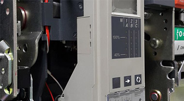
The circuit breaker needs to be in the open state, place the handle of the plug-in mechanism in the position shown in Figure 1, and then slowly put the circuit breaker into the rail groove of the base, turn the interlock device to the unlocked position, and then set the handle as shown in Figure 1. Rotate the direction of insertion to make the handle be in the insertion position as shown. At this time, the interlocking device should be automatically locked and the in-position indicating device is turned on, and the operation process of inserting the circuit breaker is completed.
2. The circuit breaker withdrawing operation process
The circuit breaker needs to be in the open state, turn the interlocking device to the unlocked position, and turn the handle according to the drawing direction shown in Figure 1. At this time, the main contact of the circuit breaker is disconnected from the main contact of the base, and the interlocking device will automatically lock Up; in order to prevent slippage, the circuit breaker cannot be withdrawn normally at this time, you need to turn the interlock device again to make it in the unlocked state, and then turn the handle according to the drawing direction as shown in the figure, and then turn the handle to the drawn position as shown. The device is withdrawn.
3. Mechanical interlocking principle of withdrawable device
The interlocking device uses a trigger type automatic locking device. When the circuit breaker moves to the disconnected position of the main circuit and the secondary circuit, the interlocking device is automatically locked; if you need to insert or pull out, you must turn the interlock knob to the unlocked position. Then push the handle to insert or withdraw; when the circuit breaker moves to the main circuit and the secondary circuit are reliably connected, the interlocking device is automatically locked, if you need to withdraw, you must turn the interlock knob to the unlocked position and then push the handle to withdraw.
4. Withdrawable device electrical interlock wiring principle
Withdrawable device is equipped with secondary wiring device. The secondary circuit wiring device adopts pin type insertion, which adopts contour positioning and has the characteristics of automatic alignment and reliable contact. The purpose of using the secondary device is to completely separate the circuit breaker and its accessories from the base of the withdrawable device during maintenance or quick replacement. The wiring method of the secondary circuit: the internal accessories of the circuit breaker are connected to the movable contact on the secondary device by the wiring piece, and the static contact corresponding to the secondary device is connected to the power distribution system by the wiring piece.
5. Withdrawable electric interlocking method
The electrical interlock circuit diagram composed of the shunt release is shown in Figure 2, and the electrical interlock circuit diagram composed of the undervoltage release is shown in Figure 3.


In the case of not hindering the function of the original shunt release or undervoltage release, borrowing one of them as a component of the electrical interlock can effectively prevent the danger caused by misoperation of the device during operation. For example: when the circuit breaker is inserted or withdrawn in the closed state, the electrical interlocking mechanism will prompt the internal accessories of the circuit breaker to operate to make it in a free trip state before the main circuit is connected or disconnected. The circuit breaker cannot be closed when the circuit is not connected reliably (indicated by the in-position indicator).
Related

Factory Address:Pudong, Shanghai, China / Jiaxing, Zhejiang, China
Technical Support:+86-400-99-02706 Email:rfq@nader-circuit-breaker.com |