Common problems of circuit breaker inter-stage coordination
When the circuit breaker is used as upper and lower protection, its action should be selective, and the upper and lower levels should cooperate with each other, and pay attention to the following issues:
1) When the upper and lower actions of the circuit breaker are selective, attention should be paid to the matching of the current release setting value and time. Generally, the setting current of the upper circuit breaker's overload long delay and short circuit short delay should not be less than the lower circuit breaker setting 1.3 times the value to ensure the action selectivity between the upper and lower levels. Under normal circumstances, the first-level circuit breaker (such as the low-voltage side of the transformer) should use the protection characteristics of overload long delay, short circuit short delay (0~0.5 s delay adjustable), and no short-circuit instantaneous release. The second-level circuit breaker should choose overload long delay, short circuit short delay, short circuit instantaneous and ground fault protection. The bus tie breaker should be equipped with overload long delay and short circuit short delay protection. There should be a difference time between the first and second short-circuit delays, which should not be less than 0.2 s.
2) When the upper stage is a selective circuit breaker and the next stage is a non-selective circuit breaker, the setting current of the short-circuit short-delay release of the upper-level circuit breaker should not be less than the setting current of the short-circuit instantaneous release of the lower-level circuit breaker 1.3 times of the current; the setting current of the instantaneous release of the upper-level circuit breaker should be greater than 1.2 times of the single-phase short-circuit current at the outlet end of the lower-level circuit breaker.
3) When both the upper and lower levels are non-selective circuit breakers, the level difference between the tripping devices of the upper and lower circuit breakers should be increased. The setting current of the long-delay release of the upper-level circuit breaker should not be less than twice the setting current of the long-delay release of the lower-level circuit breaker; the setting current of the instantaneous release of the upper-level circuit breaker should not be less than the setting current of the instantaneous release of the lower-level circuit breaker 1.4 times.
4) When the short-circuit current at the outlet of the lower-level circuit breaker is greater than the instantaneous release setting current of the upper-level circuit breaker, the lower-level circuit breaker should use a current-limiting circuit breaker to ensure the selectivity requirements.
5) When the distance between the upper and lower circuit breakers is very close, and the expected short-circuit current difference between the outlet ends is very small, the upper circuit breaker should be equipped with a short-delay trip to delay the action to ensure selective coordination.
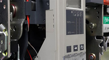
6) The setting of the trip unit and time limit of the circuit breaker can generally refer to the following principles: The setting current of the long-time trip unit can be 0.9 to 1.1 times the rated current Ie of the trip unit, and the time limit can be selected as 15 s. The setting current of the short-delay release can be selected at 3 to 5 times the rated current Ie of the release, and the time limit can be selected at 0.1 s, 0.2 s and 0.4 s. The instantaneous release setting current can be selected as 10-15 times the rated current Ie of the release.
Need to use selectivity meter and trip curve diagram Wang Dianguang/Senior Engineer Chief Engineer of Marketing Technical Support of Haige Electric Company
If the circuit breaker level coordination is replaced by the national product standard, it is the selectivity of protection. The definition and requirements in the product standard are as follows:
1) Full selectivity: GB14048-2/2.17.2 In the case of two over-current protection devices connected in series, the over-current selective protection of the protection device on the load side does not cause the action of the other protection device.
2) Partial selectivity: GB14048-2/2.17.3 In the case of two overcurrent protection devices connected in series, the protection device on the load side does not cause the other protection device to operate excessively when the protection is performed under the specified overcurrent level. Selective current protection. This overcurrent limit value is called "selective limit current Is".
How to design an economical and reliable power distribution system? First of all, the full selectivity between ACB and MCCB and MCB is easy to achieve, because ACB, MCCB and MCB belong to different use categories in the product standard, ACB is category B, and MCCB is category A. Utilizing ACB's inherent class B short-current and short-delay tripping performance and class A MCCB in series to form the so-called full selectivity. The difficulty is that the protection coordination between the upper and lower levels of similar circuit breakers cannot have full selectivity, but can only have selectivity or partial selectivity under certain limits (some discussions call it incomplete selectivity). See National Standard GB 14048-1 No. 2.5.23 Overcurrent Selectivity "The coordination of the action characteristics between two or more overcurrent protection appliances in series. When the overcurrent is within the specified range, the protection that operates within this range is specified The electrical appliances act, but other protective electrical appliances do not act". That is, there is selectivity within a certain range of the short-circuit current value, and there is no selectivity outside the range. At this time, the designer can use the tools provided in the manufacturer's product catalog to confirm the selective overcurrent range. One tool is the selectivity table, in which the selectivity limit current Is value list of all possible paired upper and lower circuit breakers is listed in kA. The designer can see from the table that the Is value of the two upper and lower circuit breakers exceeds this value and there is no selectivity. Another tool is the trip curve graph. Compare the trip curves of two upper and lower circuit breakers under one coordinate. The current value at the intersection of the two curves is Is. It is easy to know that the current value of the curve is less than Is on the graph. Be selective.
Current circuit breakers generally have current-limiting technology. In layman's terms, the current-limiting technology of circuit breakers makes the short-circuit current in the actual line not reach its expected peak value, so that the breaking capacity Icu (or Ics) can be selected to be less than the expected short-circuit current value. Device. Due to the shortening of the tripping time, the service life of the switch and the cable can be prolonged, and the investment in the circuit breaker can also be reduced. Using the upper-level circuit-breaker current limiting technology for backup protection, the lower-level circuit-breaker can have a more economical choice. Here is a new solution for designers to recommend a fully selective protection: German Higer Electric Company produces and sells a Type B Selective Main Circuit Breakers (SMCB) in Germany. This kind of SMCB and Class A miniature circuit breaker can achieve full selectivity by cooperating with the upper and lower levels, thereby avoiding the selective blind zone of Class A circuit breaker. The national standard of SMCB has been approved by the National Standards Administration of China, the standard number: GB24350—2009 "Selective Overcurrent Protection Circuit Breaker for Household and Similar Places", which took effect on August 1, 2010.
The working principle of SMCB is: when a short-circuit current occurs, the main circuit contacts of the upper-level circuit breaker (ie SMCB) are separated for a short time to achieve the purpose of current limiting. The bypass system in the body continues to flow, and the protection trip unit has not been activated. In this case, after the lower-level circuit breaker MCB has "guaranteeed" that the short-circuit current is interrupted, the main contact of the SMCB is switched on again, and the bypass system is disconnected.
Related

Factory Address:Pudong, Shanghai, China / Jiaxing, Zhejiang, China
Technical Support:+86-400-99-02706 Email:rfq@nader-circuit-breaker.com |